M3 SKY Pin I/O Description
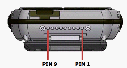
This document describes the type and usage of 9 POGO Pin connectors and 24 Pin connector of M3 SKY which is located at the bottom of the device.
1. POGO PIN Description
|
No.
|
Name
|
Connect Information
|
|
1
|
USB_DN
|
For USB data negative
|
|
2
|
USB_DP
|
For USB data positive
|
|
3
|
USB_PW
|
For USB power
|
|
4
|
DETECT
|
Active Low
|
|
5
|
RXD
|
PAD -> DCE (TTL level), Serial RXD COM8
|
|
6
|
TXD
|
PDA <- DCE (TTL level), Serial TXD COM8
|
|
7
|
TOGID
|
DC 3.6~4.2V
|
|
8
|
CHR_MNS
|
GND
|
|
9
|
+5V
|
System Power and Charging
|
2. 24 Pin Description
|
No.
|
Name
|
Connect Information
|
|
1
|
TRST
|
|
|
2
|
TMS
|
PRE_PWR
|
|
3
|
TCK
|
USB_OTGID
|
|
4
|
TDI
|
DC 5V
|
|
5
|
TDO
|
DC 5V
|
|
6
|
RXD
|
JTAG_TDI
|
|
7
|
TXD
|
JTAG_THS
|
|
8
|
RTS
|
JTAG_TCIC
|
|
9
|
CTS
|
JTAG_TDO
|
|
10
|
USB_DN
|
For USB data negative
|
|
11
|
GPS_DETECT
|
Active High
|
|
12
|
BATT_MNS
|
|
|
13
|
RXD2
|
PDA <- DM_TXD
|
|
14
|
TXD2
|
PDA -> DM_RXD
|
|
15
|
USB_DP
|
For USB data positive
|
|
16
|
USB_PW
|
For USB power
|
|
17
|
DM_RXD
|
CPU_TRST
|
|
18
|
DM_TXD
|
TEXT_POINT
|
|
19
|
BATT_MNS
|
|
|
20
|
DM_DETECT
|
Active High
|
|
21
|
BATT
|
Battery Line (MAX. 4.2V)
|
|
22
|
BATT
|
Battery Line (MAX. 4.2V)
|
|
23
|
IGT
|
GSM ON/OFF
|
|
24
|
GND
|
Power Ground
|